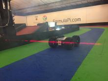
Laser Timing Rig

So that we could record the lap times for the Formula Pi Robots in the elimination rounds, we created a laser timing rig. This consists of a laser diode pointed at a photodiode. We figured we would need to be able to accurately position the pair to be pointing directly at each other, so we made some adjustable mounts with four easy to adjust screws (giving up/down and left/right movement).
Sorry for the shaky camerawork, and I never did get around to making a video of the electronics :s
The laser side just has a power connector and a resistor so that the bus supplies equal power to all 7 lasers. The photodiode side has a small circuit to trim the level at which it activates a differential amplifier. The amplifier is connected back to the Raspberry Pi with two power connectors and an A/B differential pair. The Pi is connected to a protoboard with 7 differential receivers and two DCDC power supplies (3.3V and 5V). Both sides use the same PCB (one we quickly designed) and the same PCB is populated with different components for each pair.
Installing it on to the track was easy enough, and the alignment went quite smoothly. Hooray!
At the moment, the track is using only one sensor pair. Shortly it will use 6 or 7 to be able to run sector times and automatically switch the cameras.
I shall to leave it to Arron to explain the software side of the timing rig :)


Comments
Lou0151
Fri, 27 Jul 2018 - 02:02
Permalink
Laser Timing Hardware
Hi, I would like to ask if you could share the particulars of the laser setup? The pcboard, schematics and part numbers. Thank you very much.
Add new comment